
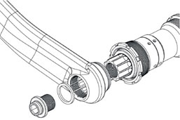
- The Inspection method described in the International Spline Interface Standard (ISIS), uses a ring gage with two steps on the front side. This Ring gage shows Go and Nogo situation in one gage.
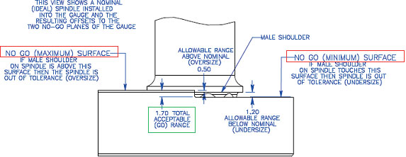
- The decisive factor is the position of the shoulder on the ISIS shaft. The location of this shoulder has to be within a range of 1.70 mm after the gage stops on the shaft. Thus, the Go situation is achieved (GO RANGE).
- If the male shoulder on spindle touches the lowest surface NO GO (MINIMUM) SURFACE on the ring gage, the spindle is to small (UNDERSIZE).
- If male shoulder on spindle is above the top surface NO GO (MAXIMUM) SURFACE of the ring gage, the spindle is out of tolerance (OVERSIZE).
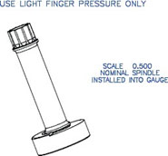
- The picture shows the ideal situation. The top surface is exceeded by 0.50 mm and still it is a distance of 1.20 mm to the lowest surface.
Pic: Copyright 2001, ISIS Drive Standard Committee
 |  |
ISIS – Difficulty
- If a dimensoin over balls is to small in section A-A for example, it will not be recognized with the ISIS gage concept. Unknown scrapped parts could be in circulation.
- The decisive factor is the position of the shoulder “Male shoulder”. Obviously, there are shafts manufactured without shoulders. In this case, the ISIS concept cannot be used anyway.
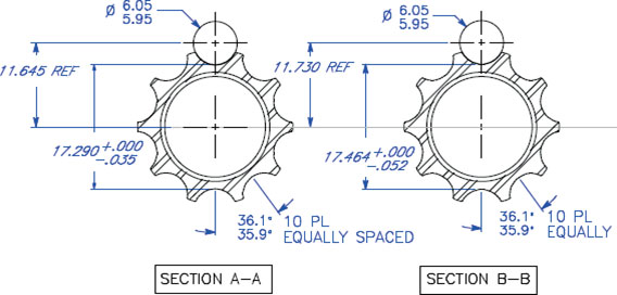
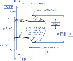
FRENCO ISIS Inspection Concept
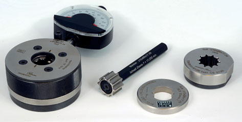
- The limits minimum and maximum will be checked separately. This means as already known in the machining element splines, that a full composite profiled Go ring gage for max. effective and a sector profiled Nogo gage for min actual will be used. This Nogo gage can figure out shafts which are too small.
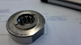
- A shaft with a male shoulder has to fit in the Go ring gage so far, that the shoulder touches the front side of the ring gage. Shafts without this shoulder will be considered to the front surface of the shaft. The front side of the shaft has to be in contact with the internal located stop in the Go ring gage. If the shaft reaches this stop, it can be clearly recognized with a sound.
- The sector profiled Nogo gage is designed accordingly, so that it can be set on the shaft, and the front side of the shaft must not exceed the end surface of the Nogo ring gage.
- As an alternative inspection method instead of the Nogo ring gage, a FRENCO indicating inspection device type AVMF 1×1 can be used. With this, a dimension over two balls can be inspected in level A-A or B-B, too. During production, a range of different sizes can be observed and controlled. The smallest dimension over balls is the min limit which is not allowed to fall below. A setting master right on this min limit is available and the dial indicator can be adjusted to zero with this setting master. By inspection of a shaft, it is not allowed to fall below this min limit. Therefore, the handling is very easy with this indicating gage.
Euro-Tech is the exclusive North American distributor of the Frenco product line. For more information visit:
www.eurotechcorp.com/Frenco

